Load balancing
Load balancing allows a stream of traffic to be divided approximately evenly among multiple egress ports. The traffic stream may come from a single ingress port or it may aggregate traffic from multiple ingress ports. Filtering may be applied to remove unwanted traffic before the remainder is load balanced.
Load balancing becomes available on KARINCA devices when an Aggregation & Filtering & Load Balancing Feature Pack has been installed. Please contact your Angora Networks reseller if you wish to install this feature.
Load balancing on KARINCA
Traffic is divided among the load balancing ports by examining one or more headers in each packet from the stream. The headers to be examined are user-configurable, with nine choices available initially.
The list of headers that may be used for load balancing is as follows:
- VLAN number
- MAC source address
- MAC destination address
- IPv4 source address
- IPv4 destination address
- IPv6 source address
- IPv6 destination address
- TCP/UDP source port
- TCP/UDP destination port
Egress ports for load balanced groups may still be used as destinations for the normal mapping and filtering functions. For example, if tools are monitoring a protocol that has separate control and data channels, it is possible to load balance the data channel traffic across a set of tool ports, but still to replicate all control channel data to all of those tool ports at the same time.
Load-balancing scalability
KARINCA supports up to eight independent load balancing groups. The packet headers used to balance each group may be different, but there is a limit of three headers per group.
There is no fixed limit on how many ingress ports may be aggregated to feed into a group, and there is no fixed limit on how many egress ports a group’s traffic may be shared among. However, in practice the possible configurations will be limited by system memory. Using many groups, many packet headers and many ports all at once is not possible.
Load balancing consistency
Packets with the same header values are guaranteed to go to the same egress port. For example, if IPv4 source and destination addresses are used for balancing, all traffic from address A to address B will be sent to the same egress port. However, there is no guarantee traffic from address B to address A will also be sent to that same egress port.
Load balancing non-exclusivity
Egress ports for load balanced groups may still be used as destinations for the normal mapping and filtering functions
of KARINCA systems. For example, if tools are monitoring a protocol that has separate control and data channels, it is possible to load balance the data channel traffic across a set of tool ports, but still to replicate all control channel data to all of those tool ports at the same time.
Load balancing – Best practices and limitations
When using the load balancing feature, we recommend you follow our suggested best practises and take note of the limitations that apply.
Best practices
The following best practises can be used to produce good results when setting up load balancing on KARINCA-1048-6Cdevices.
- Unless there is a compelling reason, you should restrict load balancing to one or two headers. Any more than two headers requires considerably more system resources when running.
- If possible, select headers that will vary randomly for the expected traffic. In the majority of cases, two such headers will provide effective balancing, and in some cases one may be enough. Note that incoming packets with the same values for all of the headers selected for balancing will always be directed to the same egress port within the load balanced group.
- If balancing across many ports or if the system has many other maps configured, if possible, use only a single load balancing header to avoid overloading the system.
- Groups of two or four egress ports will give the most even output and will be the most memory-efficient.
- Where possible, apply filters to the ingress ports to restrict the stream to just those packets required for load balancing.
For example, if you wish to balance on headers below layers 2, that is, the various IP address and port headers, set up a filter that restricts packets to just those headers.
Limitations
The following limitations apply when using load balancing on KARINCA-1048-6Cdevices.
- Load balancing needs variation in the selected header fields of incoming traffic to work properly. For example, if the IPv4 source and destination addresses are selected, but all incoming traffic is between the same pair of addresses, the balancing will not be effective. All packets would be sent to the same tool.
- The balance is only an approximation, even with ideal incoming traffic. In general, it is not guaranteed that each of n egress ports will receive exactly 1/nof the incoming packets. Some ports may receive 50% more packets than others in the worst case. However, as long as two or more header fields are selected, a very even spread should be achieved if the incoming traffic is suitable.
- There is no failsafe or standby capability for tools that fail. If a group balances traffic among, say, four tools and the link to one tool goes down, those packets will be dropped. You may reconfigure the system to balance across the remaining three tools, but this is not automatic.
- The system cannot balance traffic from one ingress port using IPv4 and IPv6 address fields together. This mirrors the existing limitation on applying both IPv4 and IPv6 filters to maps from the same port.
Setting up load balancing
To set up load balancing, map source ports to a Load Balancer group and map the Load Balancer group to destination ports. Configure the Load Balancer group with the headers that you want to balance against.
The following example load balances ports 1C, 1D, 2C and 2D from source ports 3A and 3B. It uses the packet’s IPv4 source and Layer 4 port source for the load balancing data.
1. Map port 3A to 3B and 3B to 3A.
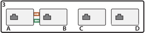
Map A and B ports
2. Select ports 3A and 3B and then drag to load balancing group LB1.
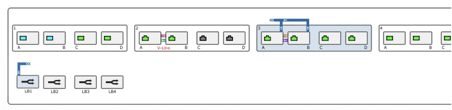
Map ports 3A, 3B to LB1
3. Optionally add filters to remove unwanted packets prior to load balancing.
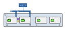
Add filters to remove unwanted packets
4. Select ports 1C, 1D, 2C, 2D, then drag LB1 to any one of the selected ports.
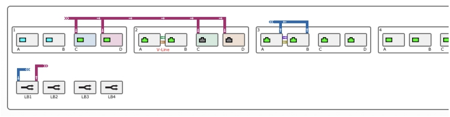
Map LB1 to ports 1C, 1D, 2C, 2D
5. Click on the Load Balancer Group (LB1).
6. Choose up to three headers for the load balancing group. Note that to ensure an even load distribution, the headers chosen must provide a variety of data for the expected packets.
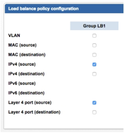
Choose load balancing policy headers
7. Click Review/apply and review pending changes. To apply these changes to the system, click Apply changes or click ‘X‘ to cancel.
The complete set of CLI commands for the example configuration are shown below.
CONTROLLER>set map 3a to 3b
CONTROLLER>set map 3b to 3a
CONTROLLER>set map 3A 3B to LB1 require HTTP
CONTROLLER>set LB1 to 1C 1D 2C 2D
CONTROLLER>set lbheaders LB1 ipv4_src port_dest
CONTROLLER>commit
Committing maps
Committing filters
Committing load balance policy headers
Leave A Comment?