List of supplied components
The following components have been supplied with your KARINCA-1048-6C system.
- 1 x KARINCA-1048-6C1U chassis.
- 1 x set of chassis rack ears.
- 2 x power leads.
Please contact Angora Networks if any item is missing from the package.
Installing the chassis
To prevent unregulated access, KARINCA chassis should be installed in a secure server rack with access to authorized personnel only.
Static electricity can damage sensitive electronic components. To discharge static, fit an antistatic wrist-strap or touch a bare metal surface before handling KARINCA-1048-6C components.
1. Unpack all parts onto a clean workbench for inspection.
2. Carefully check all parts against your order. If any parts are missing or have become damaged during shipping, please report it immediately to Angora Networks.
3. Attach the rack ears to the sides of the chassis using the supplied screws.
4. Install the chassis in a 19″ server rack. The chassis occupies one rack unit. Be sure to leave enough room for all the cable connections (front and back), and for proper airflow and ventilation around the chassis.
5. Depending on whether your chassis is AC or DC powered, plug the chassis into an AC 100V-240V or a DC -42V to -63V supply. If your chassis has dual power sockets, make sure they are connected to independent supplies to ensure the chassis is able to remain powered should either suffer a power cut.
6. Turn on the chassis power switch(es) to start the system. Management interfaces will be available within two minutes. Data ports will immediately begin to pass traffic.
7. Connect management cables to the management ports, as described in Cabling for administrative connections
Cabling for administrative connections
KARINCA provides dual administration ports for networked or serial access to the management interfaces. In most cases, users will connect to the system remotely over a network. When first setting up, you may need to use the CONSOLE in order to configure the network interface address.
KARINCA-1048-6Cprovides the following administration ports:
MGMT port This port allows remote network connections to the KARINCA-1048-6C web UI and CLI management interfaces
CONSOLE port This port allows direct, serial connections to the command line interface (CLI).
Management port cabling for network access
The MGMT port provides network access to the KARINCA-1048-6Cweb UI and CLI management interfaces.
1. Connect an Ethernet cable to the MGMT port, and the other end to your network switch.
2. Connect the Ethernet cable to a switch that allows access to networked management workstations. The default IP address for KARINCA-1048-6C is 192.168.254.100.
Management port cabling for serial access
The CONSOLE port provides serial access to the CLI from a PC that is running terminal emulation software.
To complete this task, you will need:
- The supplied DE-9 female to 8P8C (RJ45) serial management cable cable (see figure below). This cable is also known as a Cisco Console Cable, Cisco Management Cable, Yost Serial Cable, or Rollover Cable.
- A PC with a serial COM port.
- Terminal emulation software, such as TeraTerm, MobaXterm, Secure CRT
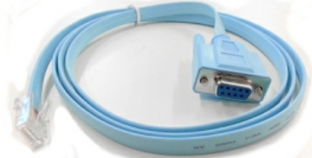
Figure 1: DE-9 female to 8P8C (RJ45) serial management cable
1. Connect the RJ45 end of the DE-9 female to 8P8C (RJ45) serial management cable to the serial CONSOLE port.
2. On your PC, open your preferred terminal emulation client and make sure the COM settings are as follows:
- Baud Rate: 9600 bps
- Data bits: 8
- Stop bits: 1
- Parity: None
3. If the COM settings are correct, the KARINCA-1048-6C username prompt will be displayed on your terminal screen.
4. To log on, enter your KARINCA-1048-6C administrator username and password. If login is successful,
CONTROLLER>
prompt is displayed, as shown below.
Username :admin
Password :*****
Login over serial connection Command Line Parser
Built on Sep 25 2017 at 15:29:17 from svn revision 263M Running at Authorization level 3
User admin logged in from serial-connection
CONTROLLER>
5. Enter KARINCA-1048-6C CLI commands as required. Entering help outputs a list of available commands and other useful information
6. To logout and allow other users to access the management systems, enter exit. Note that there is an automatic default timeout of 15 minutes for idle connections.
Connecting to the system
You can connect to the KARINCA management interfaces using a web browser or a terminal client. Both methods use secure communication channels (HTTPS and SSH), and require users to be authenticated before access is granted. Only one user may access the management interfaces at a time.
Connecting from a web browser
Connecting to the management port from a web browser provides user access to the KARINCA web user interface. This allows the device to be managed using an intuitive, graphical user interface. In particular, the integrated drag and drop engine allows the easy creation of port maps by dragging from one port to another, and the application of filters by clicking on a map and choosing a filter to apply.
1. Open up a web browser and enter the IP address for KARINCA. If the address is correct, the KARINCA login page will be displayed. See the following figure.
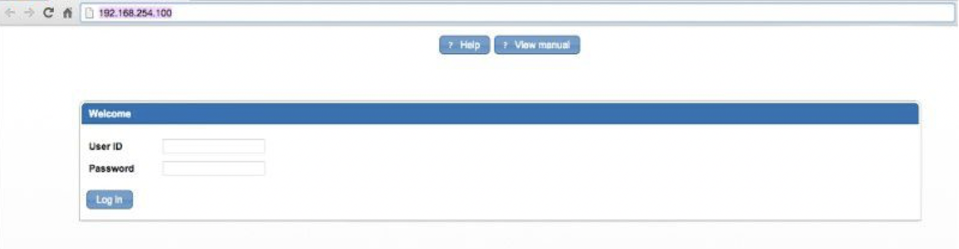
Figure 2: The KARINCA web UI login page
2. Enter the KARINCA user ID and password, and then click Log in to access the web UI, as shown in the following figure
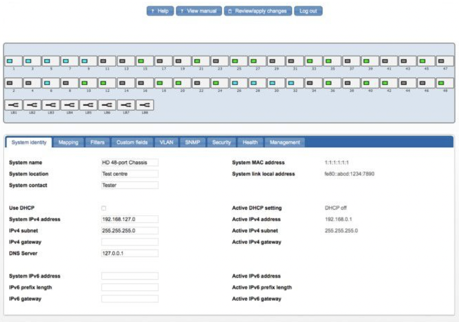
Figure 3: The KARINCA web UI
3. Use the device schematic to configure the system settings, ports, maps, and filters as follows:
Click anywhere within the chassis area (the blue area in the figure) to access these system-wide options:
- System identity Settings for system name, contact, location, and network interface addresses (IPv4 and IPv6), as well as information for the current IP address and MAC.
- Mapping
- Filters
- Custom fields
- VLAN Lists TPID and other options for VLAN tagging.
- SNMP Settings for configuring SNMP and enabling which notifications to send when an alert is generated.
- Security Settings for configuring RADIUS and TACACS+ Authentication and Accounting servers.
- Health Provides information about the health of the system (uptime, temperature, firmware revision, and so on), and allows setting of the upper temperature threshold for the triggering of SNMP health notifications, and the timeout period for rule generation for when applying maps and filters.
- Management Provides options for upgrading system firmware, installing Feature Packs, saving configurations, uploading a custom SSL certificate, and for rebooting the system.
Click on a port to access the following per-port options:
Port configuration Settings for port description, usage, locking, force link up, and other communication options for ports which allow this type of configuration.
- VLAN Settings for VLAN port tagging and QinQ packets.
- Traffic Provides traffic statistics, including number of bytes and packets in and out, and overall utilization as a percentage of the port capacity.
- Errors Provides statistics on bad packets and other transmission errors received.
- SFP Provides information for SFP ports, including physical type, model, vendor information, and electrical properties.
- Health Settings for traffic high and low thresholds that would trigger an SNMP health notification if exceeded.
Click on a port (ALT-click for multiple ports) and drag to another port to create a mapping between them.
Click on a port map to set up packet filters.
4. If you make changes to the configuration, click the Review/apply changes button to review and apply them.
5. Click the Log out button when you have finished updating the system. This allows other users to access the system, although there is a 15 minute idle timeout if you forget to logout.
Connecting from a terminal client
You can connect from a terminal client and use KARINCA commands to manage the system.
To connect from a terminal client, you’ll need:
Your KARINCA username and password.
The network address for KARINCA-1048-6C.
A terminal client that supports Secure Shell (SSH). On Linux and Mac OS, you can use the native Terminal client. On Windows, you can use a third-party SSH client such as TeraTerm, MobaXterm, SecureCRT
1. In the terminal client, enter the following command:
$ssh [email protected]
where 192.168.254.100 is the network address of KARINCA
2. If prompted, enter yes to add KARINCA-1048-6Cto the list of known hosts:
The authenticity of host '192.168.254.100' can't be established.
RSA key fingerprint is 9a:30:7b:95:ec:b4:fe:53:e1:a4:42:69:4f:15:5c:1a.
Are you sure you want to continue connecting (yes/no)? yes
Warning: Permanently added '192.168.254.100' (RSA) to the list of known hosts.
3. When prompted, type your KARINCA password and press enter.
CONTROLLER>
prompt is displayed after logging in:
[email protected]’s password:******
CONTROLLER>
4. Enter commands to query or configure the system as required. You can get help on which commands are available by entering the help command.
5. When you have finished, enter exit or quit to close the connection and exit the CLI.
Configuring network settings
You may need to configure the network address to gain access to the management interfaces from networked management stations. By default, the system is assigned the static IP address 192.168.254.0, as well as an IPv6 link-local address that can be obtained from the System identity tab, as shown in the figure below.
If necessary, the network address can be configured in either of the following ways:
- Manual — You have to input the information, including system address and subnet mask. If your management station is not in the same IP subnet as the unit, you will also need to specify the default gateway router.
- Dynamic — The unit can send IPv4 configuration requests to a DHCP address allocation server on the network.
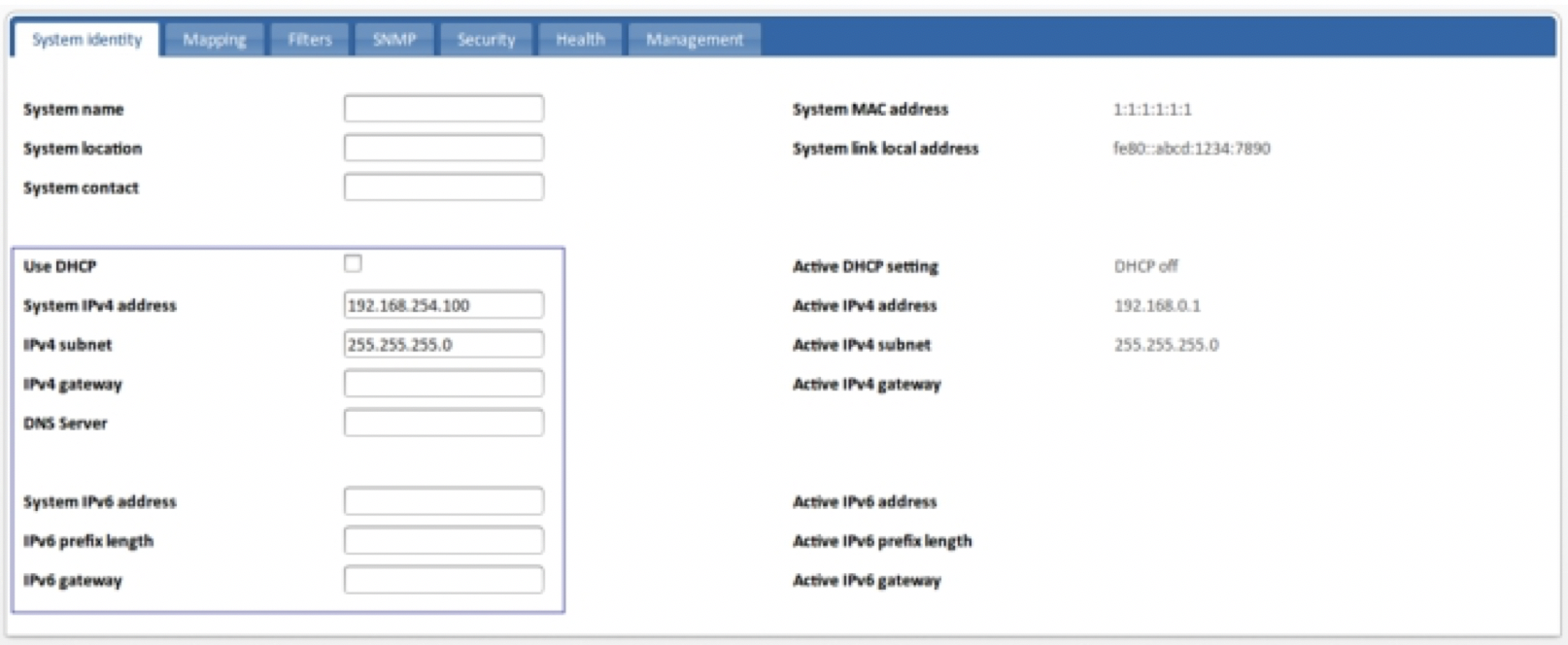
Figure 4: System identity tab network address options
Manual network configuration
You can manually assign an IPv4 or IPv6 addresses (or both) to the device. You may also need to specify a default gateway that resides between this device and management stations that exist on another network segment.
1. Click on the chassis and select the System identity tab.
2. Turn off the Use DHCP checkbox.
3. If assigning an IPv4 address, enter the IPv4 parameters.
- System IPv4 address—Enter the IPv4 network address in dotted-decimal format (a.b.c.d).
- IPv4 subnet—Enter the network address subnet mask in dotted-decimal format (a.b.c.d).
- IPv4 gateway—(Optional) Enter the IPv4 address of a default gateway that resides between this device and management stations that exist on another network segment. The gateway address must be specified in dotted- decimal format (a.b.c.d).
- DNS Server—(Optional) Enter the IPv4 address of a default DNS server in dotted-decimal format (a.b.c.d).
4. If assigning an IPv6 address, enter the IPv6 parameters.
- System IPv6 address—Enter the network interface IPv6 address, in standard IPv6 format, such as 2001:db8::52:0:1
- IPv6 prefix length—Enter the network prefix length. The value must be in the range 16–124.
- IPv6 gateway—Enter the network gateway IPv6 address.
5. Click Review/apply, review the changes you have made, and then click Apply to implement the new settings. After a quick delay you will be logged out as changes are implemented. You must now use the new IP address to connect to the device.
Dynamic network configuration
The system supports dynamically allocated IPv4 network address values from a network DHCP address allocation server. DHCP values can include the IP address, subnet mask, and default gateway. IPv6 address allocation is not supported by the system.
1. Click on the chassis and select the Security tab.
2. Select the Use DHCP checkbox.
3. Click Review/apply, review the changes you have made, and then click Apply to implement the new settings. After a short delay you will be logged out while changes are implemented. The system will begin broadcasting service requests.
Leave A Comment?