VLAN tagging
KARINCA supports the passing of VLAN double-tagged (QinQ) packets, and port tagging on ingress ports to identify the original source port for later reference.
Support for double-tagged (QinQ) packets
KARINCA-1048-6Csupports the passing of VLAN double-tagged (called QinQ) packets. Double-tagged packets may be aggregated or replicated in the normal way.
The following system-wide settings are associated with QinQ packets:
- TPIDs, which are used to set the service ID Tag (S-Tag), a customer ID Tag (C-Tag), and a port stamping ID Tag (P-Tag) that is used to push an additional VLAN header with a distinct TPID.
- Ordering convention (S outer/C inner, or C outer/S inner) used on the network; egress packet headers will be in this order for double-tagged packets.
- Whether filtering and load balancing on VLAN-related headers look up the S-Tag or the C-Tag; either can be used, but you can’t filter on both C-Tag fields and S-Tag fields at the same time.
Filtering on VLAN headers
When filtering on VLAN-related headers, a possible scenario may arise whereby you have configured to filter on S-Tag as the global preference but then traffic is received with just a single VLAN Tag that is effectively a C-Tag.
In this scenario, the packet will be treated as not matching that filter, since it doesn’t have an S-Tag. If the filter was required by that map then the packet will not be passed. If the filter was excluded then the packet will still be passed, other filters permitting.
Port P-Tags take precedence over global P-Tags
Settings relating to P-Tags configured on individual ports take precedence over the global preferences.
That is, if an incoming packet has a single VLAN header but it is a P-Tag added by the system rather than a normal C- Tag, and if the ingress port has the “filter on P-Tag” option set, then any filters on VLAN ID will still pick up the ID from the P-Tag header for that packet as usual.
Port tagging
Packets may be tagged on ingress to identify the original source port for later reference. Typically this would be done prior to aggregating traffic from multiple ingress ports to be filtered, load balanced or sent to external tools as a merged stream.
The tagging works by pushing an additional VLAN header with a distinct TPID. Angora Networks refer to this header as the port tag or ‘P-Tag’. (Note: This term is unrelated to any other networking convention that may have also used this term.)
Each ingress port may then specify its own VLAN ID to use in that header, allowing traffic from different ports to be distinguished. It is also possible for multiple ingress ports to use the same VLAN ID if required, for example in a live/ standby situation if you want both ports to indicate the same origin.
When setting up port tagging, you use the following configuration settings:
• C-Tag, S-Tag and P-Tag TPIDs – Global settings that allows you to specify the TPIDs that are used to identify C-Tag,
S-Tag, and P-Tag VLAN headers.
• Ingress P-Tag – A port setting that allows you to indicate which VLAN ID to set for a port (blank means don’t set a tag
at all).
• Egress Tagging – A port setting that allows a three-way choice between “Preserve existing”, “Push P-Tag” and “Pop
outer”.
• Filter on P-Tag – A port setting which means ingress traffic on this port should check the P-Tag for any filtering or
load balancing on VLAN-related headers (overriding the system-wide default of S-Tag or C-Tag for traffic from that specific port).
The Ingress P-Tag and Egress Tagging settings must be properly co-ordinated for the port tagging feature to work. Specifically, any ingress port that has an Ingress P-Tag set must only send traffic to egress ports that have Egress Tagging set to “Push P-Tag”, and any egress port that has Egress Tagging set to “Push P-Tag” must only receive traffic from ingress ports that do set an Ingress P-Tag.
That is, either you’re working with port tagging on or not, but all connected ingress and egress ports must be consistent about it. It is however possible for some ingress ports to use the port tagging feature with all of their respective tools, while other ingress ports that ultimately send traffic to other tools do not stamp the packets with a P-Tag.
Port tagging use-case example
One common use-case for the port tagging feature is aggregating incoming traffic, sending the merged stream through an in-line tool such as an IPS (or load balancing it across a pool of such tools), and then having the traffic that the tool passes come back into KARINCA-1048-6Ca second time and using the P-Tag to separate the original streams again for further actions or forwarding.
The following figure shows the traffic flow through such a scenario, with labels added to show the possible VLAN tagging values to enable it. The set up for this configuration is described below.
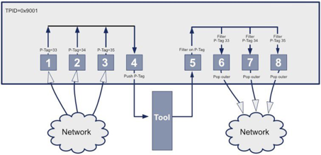
Figure 1 – Tagging aggregated traffic, outputting to a tool, then separating into final streams for output
Configuring VLAN port tagging
The following procedure describes how to set up KARINCA-1048-6Cfor the scenario described in Port tagging use-case example on page 50. You should adjust the given values to match your own port tagging requirements.
1. Set a global P-Tag TPID that will be used to push an additional VLAN header, as follows:
a) Click on the chassis and select the VLAN tab.
b) Specify the TPIDs that are used to identify C-Tag, S-Tag, and P-Tag VLAN headers. See the following figure. There are some VIDs that should be avoided as they have special significance in some networking devices. For example, VID 0 is normally reserved for priority-tagged packets, and VID 1 is reserved by many switch devices for management purposes in connection with the native VLAN.
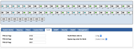
Figure 2 – Setting the TPID (P-Tag)
2. For each of the network ingress ports (1, 2, and 3), set a distinct ingress P-Tag (33, 34, 35), as follows:
a) Click on port 1 to select it, and then hold <Shift> and click ports 2 and 3 to select all three ports.
b) Select the VLAN tab. c) In the Ingress P-Tag field, enter P-Tag values for each port. For example 33, 34, and 35. See the following figure.
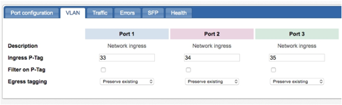
Figure 3 – Set the Ingress P-Tag for the network ingress ports
3. Aggregate the incoming traffic and forward it to a tool port or load balanced group of tool ports.
a) Click on port 1 to select it, and then hold <Shift> and click ports 2 and 3 to select all three ports.
b) Drag any of the selected ports to port 4. This creates an aggregation of ingress ports 1–3 to egress port 4. See the following figure.
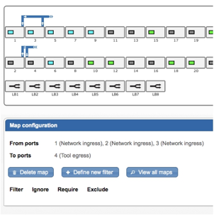
Figure 4 – Aggregate the ingress ports (1, 2, and 3) to the tool ingress port (4).
4. On the egress port that is connected to the tool (port 4), set the Egress tagging option to Push P-Tag.
a) Click on port 4 to select it, and then select the VLAN tab.
b) From the Egress tagging menu, select Push P-Tag. See the following figure.
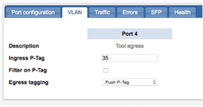
Figure 5 – Select Push P-Tag from the Egress tagging menu
The aggregated stream is sent out to the tool and some or all of it comes back on new ingress ports.
5. On the ingress port (5) where traffic returns from the tool, enable the Filter on P-Tag setting.
a) Click on port 5 to select it, and then select the VLAN tab.
b) Click the Filter on P-Tag option to enable it, as shown in the following figure.
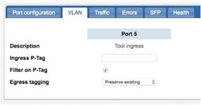
Figure 6 – Enable Filter on P-Tag egress port (5) from the tool
6. Add maps that including filtering on the VLAN ID to separate traffic from the above ingress port based on the original
ingress port from its first pass through the KARINCA-1048-6C, and direct each stream to the required final egress ports (6, 7,
8) in the normal way. Additional filtering and/or load balancing may also be used as required.
a) Click on port 5, then drag it to port 6 to create a new map.
b) Click on the new map and select Define new filter.
c) Enter a suitable name for the filter, for example “VID 33”.
d) For VLAN tag, select Match and enter a value of 33. Leave all other options at their defaults, as shown in the following figure.
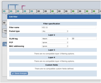
Figure 7 – Defining a VLAN filter for a VLAN tag
e) Click Save changes.
f) With port 5 → 6 map still selected, from the list of available filters, select the Require option for the filter you just created (“VID 33”).
g) Repeat these steps for the other egress ports (5 → 7 and 5 → 8). Add VLAN ‘require’ filters to each of these maps that match for values of VLAN ID 34 and 35. The following figure shows the completed configuration.
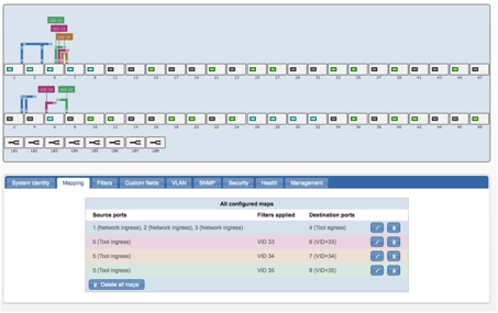
Figure 8 – Add maps and filters to the tool egress port (5) to separate the VLAN traffic to the final destination ports (6, 7, 8)
7. On the final egress port (6, 7, 8), set Egress Tagging to Pop outer, thus removing the extra P-Tag that was pushed earlier and leaving the packets back in their original format before egress to the final tools.
a) Select port 6 then hold <Shift> and select ports 7 and 8. These ports will be connected to the final traffic destinations.
b) Select the VLAN tab.
c) For the three ports, select Pop outer from the Egress tagging menu. See the following figure.
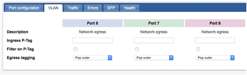
Figure 9 – Select Pop outer for each of the final egress ports (6, 7, 8)
8. Click Review/apply and review pending changes. To apply these changes to the system, click Apply changes or click ‘X‘ to cancel.
The equivalent CLI commands to enable the example configuration are as follows:
CONTROLLER>set tag tpid P 0x9001
CONTROLLER> set map 1 2 3 to 4
CONTROLLER> set tag ingress 1 to 3 on 33
CONTROLLER> set port 4 togPortStamp on
CONTROLLER> set filter f33 any vlan 33
CONTROLLER> set map 5 to 6 require f33
CONTROLLER> set filter f34 any vlan 34
CONTROLLER> set map 5 to 7 require f34
CONTROLLER> set filter f35 any vlan 35
CONTROLLER> set map 5 to 8 require f35
CONTROLLER> set port 5 filterOnVlan on
CONTROLLER> set port 6 popEgressTag on
CONTROLLER> set port 7 popEgressTag on
CONTROLLER> set port 8 popEgressTag on
CONTROLLER> commit
Leave A Comment?