KARINCA-1048-6C is available in a 54-port chassis version. This includes 48 ports of SFP28 ports supporting line speeds up to 25G bps, and 6 ports of QSFP28 ports supporting line speeds of 40G bps and 100G bps. This chapter describes how to configure ports, map them to other ports in order to transport data streams from live ingress ports to tool egress ports, and how to view port traffic statistics.
Configuring port settings
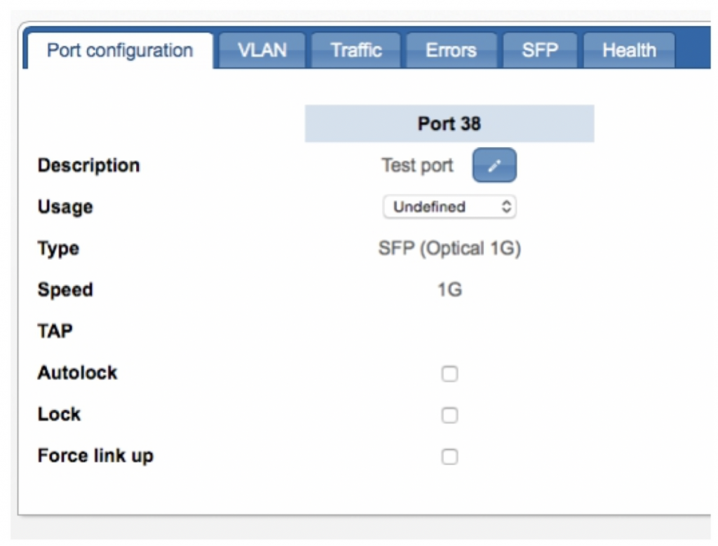
Port settings include a description field and usage setting. For security, ports that are not used can be locked to prevent unauthorized usage, and autolock can be enabled to automatically lock a port following a link down. A force link up option forces the port UP when no Autoneg packets are seen on the live network.
1. Click on the port(s) you want to configure.
2. In the Port Configuration tab, specify the appropriate port options as follows:
- Description Enter the port user-defined name or comment.
- Usage Select whether the port is connected to a live network (Network), is connected to a network tool (Tool), or is currently not connected (Unknown)
- Speed Select the configured rate for the port, either 1G, 10G, 25G, 40G or 100G.
- Autolock Select the check box to enable automatic locking of the port when a link-down status is detected. If triggered, for instance by the removal of a cable at either end of the link, the port immediately locks so no traffic passes in or out. To unlock the port after an autolock, re-attach the cable and then clear the Lock checkbox.
- Lock Select the check box to lock the port. A locked port will not pass traffic in or out.
- Force link up Enable this option to force a port UP. This option can be used when connecting to an already
- linked port (using an optical splitter) and the port sees no Auto-negotiation packets, causing the port to remain DOWN.
3. Click Review/apply and review pending changes. To apply these changes to the system, click Apply changes or click ‘X‘ to cancel.
Configuring port traffic thresholds
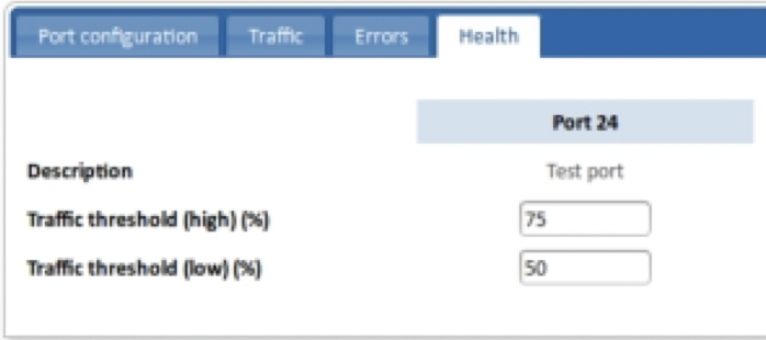
Traffic thresholds can be set on each port to warn when traffic levels are reaching the port’s maximum carrying capacity. Should the traffic level exceed the high threshold level, an SNMP system notification will be sent to all configured SNMP hosts. The warning will be cleared when the level falls below the low threshold level (do not set the low threshold value too close to the high value or ‘fluttering’ may occur, whereby notifications are continually being sent).
Port traffic thresholds do not cause port throttling (discarding of packets) to occur when the high threshold level is exceeded. Packets will only be discarded if the maximum carrying capacity of the port is surpassed.
1. Click on the port to access port information and configuration options. Multiple ports can be selected by holding down <Shift> and clicking on additional ports.
2. Click on the Health tab. The port health options are displayed.
3. Enter percentage values (of the overall port capacity) for Traffic threshold (high) % and Traffic threshold (low) %. A notification is generated when the level is exceeded, thus setting values of 0 (low threshold) or 100 (high threshold) prevents notifications being generated. See Defining notification (trap) settings on page 63 for information on configuring notifications and hosts.
4. Click Review/apply and review pending changes. To apply these changes to the system, click Apply changes or click ‘X‘ to cancel.
Creating port maps
Create port maps to form paths between source/ingress ports connected to a network to destination/egress ports connected to network tools. Maps can be created between any two ports, regardless of their physical types, properties, or configuration settings. On systems that support load balancing, use maps to connect ingress ports with load balancer groups, and load balancer groups with egress ports.
Map dependency
Maps are handled independently of each other by the system. If a source port transfers packets to several destination ports, the system will produce copies of the packets and transmit them to all connected ports. An exception however is when the same source and destination ports are connected by two or more maps (you may want to use this type of mapping so that different filters can be applied to each map). In this case, assuming the packet wasn’t’ removed by a filter, the system only delivers one copy of the packet to the destination port to prevent multiple copies of it being received.
Packets will be dropped if a port becomes overloaded. Be especially careful not to overload ports when aggregating links or moving traffic from 10G ports to 1G ports. Use filters where necessary to reduce the amount of traffic to within the carrying capacity of the port. See Using filters on page 41 for details.
Supported map configurations
The KARINCA-1048-6Csystem supports the following map configurations:
• One-to-one maps In the web UI, select an ingress port and drag to an egress port:
The equivalent CLI command for the example shown is:
CONTROLLER>set map 1 to 7
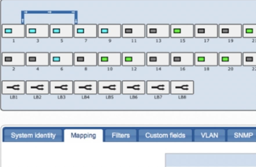
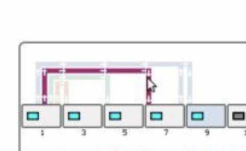
• One-to-many maps Also called a port replication or port splitting map. In the web UI, select several egress ports then drag an ingress port to any one of the selected ports:
The equivalent CLI command for the example shown is:
CONTROLLER>set map 1 to 5 9 13
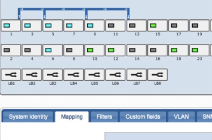
• Many-to-one maps Also called a port aggregation map. In the web UI, select several ingress ports and drag any one to an egress port. If necessary, apply filter(s) to ensure the aggregated traffic stream remains below the capacity of the receiving egress port (see Using filters on page 41 for more information):
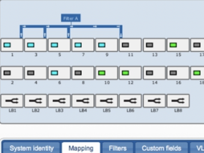
The equivalent CLI command for the example shown is:
CONTROLLER>set map 1 3 5 to 11 require Filter A
Many-to-many maps are not explicitly supported, but you can achieve the same effect using several aggregation and replication maps.
Hovering over a map causes all other maps to become dimmed, allowing you to see the starting and ending ports of the map more easily.
Editing maps
You can edit existing maps as follows:
- Drag from a port to an existing map line to add an extra source port. (Only applies if the map is currently one-to-one or many-to-one; you cannot create a many-to-many map this way.)
- Drag from an existing map line to a port to add an extra destination port. (Only applies if the map is currently one-to-
- one or one-to-many; you cannot create a many-to-many map this way.)
- Press <Alt> while dragging to remove respectively a source or destination port from an existing map. (This will remove the entire map if it is the last source or destination port.)
Viewing port statistics
For each port, the system provides details for the total number of bytes sent and received, port utilization percentages, undersized and fragmented packet errors, and other statistical information. For SFP ports, the system also provides transceiver and physical link information.
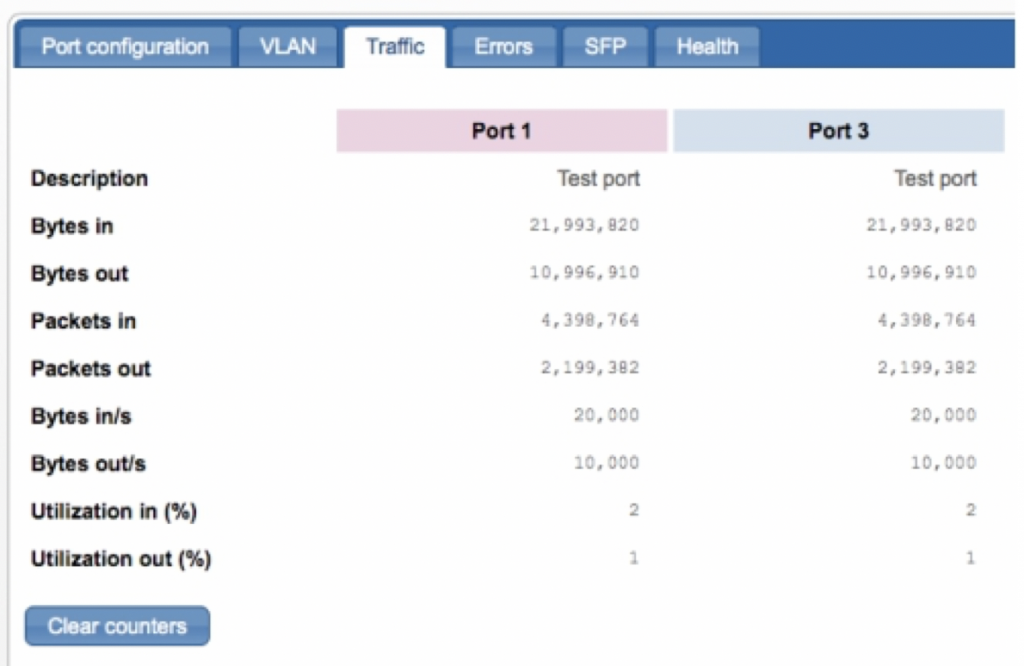
Viewing traffic statistics
The Traffic tab shows accumulated packet statistics for the selected port(s) since the last reboot or counter reset.
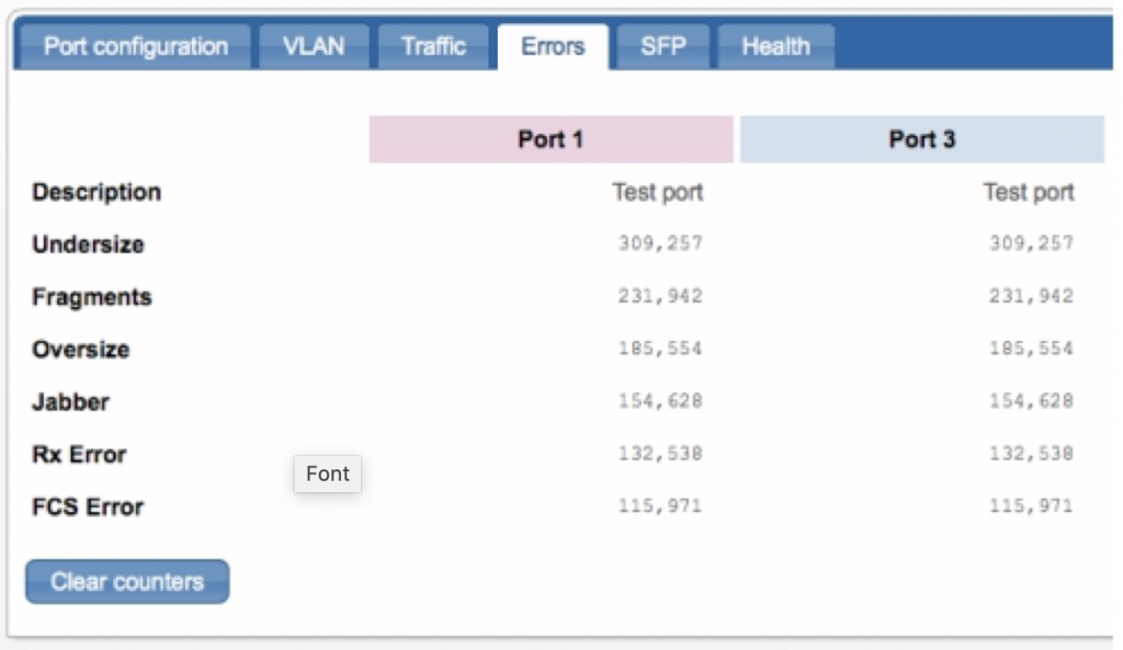
Viewing errors statistics
The Errors tab shows various accumulated packet errors since the last reboot or counter reset.
Statistics for the following packet errors are available:
- Undersize Number of undersized packets (less than 64 octets) received.
- Fragments Number of fragments (packets with less than 64 octets, excluding framing bits, but including FCS octets) received.
- Oversize Number of packets over the MRU size received.
- Jabber Total number of received packets that were longer than the MRU. This number excludes frame bits, but includes FCS octets that had either a bad FCS (Frame Check Sequence) with an integral number of octets (FCS Error) or a bad FCS with a non-integral octet (Alignment Error) number. A Jabber packet is defined as an Ethernet frame that satisfies the following criteria:
- Packet data length is greater than MRU
- Packet has an invalid CRC
- Rx Error Event has not been detected
- Rx Error—Number of transmission errors received.
- FCS Error—Number of frame checksum errors received.
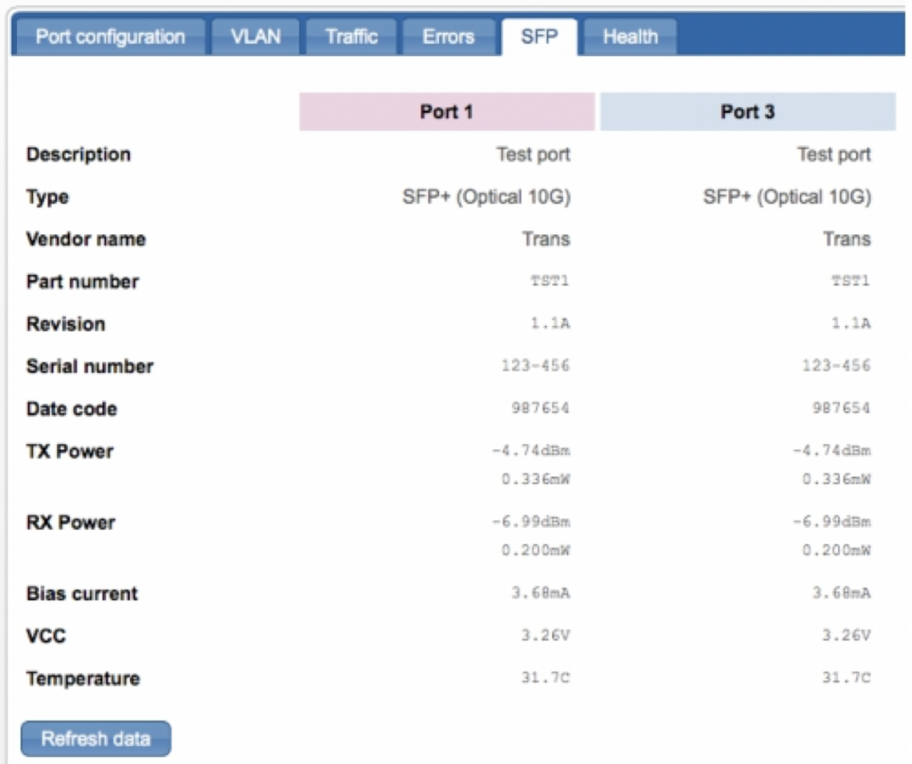
Viewing SFP information
The SFP tab shows information about the transceiver and physical link for the selected SFP port(s).
Leave A Comment?