Viewing health information
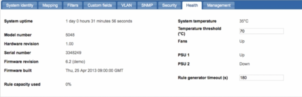
Health information is available in the web UI after clicking on the chassis area and selecting the Health tab. In the command line interface, enter the show system command to obtain health information.
Health information in the CLI:
CONTROLLER>show status
Power Supply 1: UP Power Supply 2: DOWN Fan 1: UP
Chassis Type: 5060 Model: 5060
Serial Number: 5000301 Firmware Revision: 6.2022d4
Firmware Built: Wed 15 Jul 2015 12:03:42 Hardware Revision: 1.00
Up Time: 2 days 11 hours 14 mins 56 secs System Temperature: 38
System Temperature High Threshold: 70 Rule capacity used: 0%
The following health information is available:
- Up time – Time since the last start up.
- Model – Chassis model number.
- Hardware revision – Chassis revision number.
- Serial number – Chassis serial number.
- Firmware revision – Version of the firmware installed.
- Firmware built – Date when the firmware was created.
- Rule capacity used – Percentage used of the available rule capacity for maps and filters.
- System temperature – Chassis temperature, in centigrade.
- Fans – Up/down status of the internal cooling fan(s).
- Power supply – Up/down status of the PSU unit(s).
The following user-configurable values can be set by Administrators:
- Temperature threshold – Determines the chassis temperature to trigger SNMP health notifications.
- Rule generator timeout – Determines the timeout for the Auto Rule Generator when applying or committing maps and filters to the system. Users can set a lower value if complex configurations are taking too long to apply. In this case, the apply/commit will fail and control of the UI will be returned to the user so they can make changes to the configuration.
Managing local users
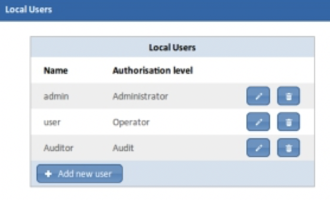
Local users are directly authenticated by the device, rather than by an external RADIUS/TACACS+ Authentication Server. When setting up a local user, you need to provide a username, a password, and an authorization level, either Administrator, Operator, or Auditor. The authorization level is a security feature which limits the user to certain management functionality, as follows:
- Administrators have full access to all system and port settings.
- Operators have access to port settings only.
- Auditors have read-only access to system and port settings.
Local users are managed from the Local Users list, which is accessible from the Security tab after clicking Configure local users.
Adding local users
1. Click on the chassis and select the Security tab.
2. Click Configure local users. The Local Users list displays.
3. Click Add new user, or to modify an existing user, click . The Add/Edit user dialog displays, show below.
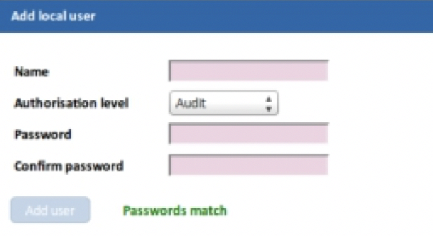
4. Enter the parameters:
- Name—Enter a new username. Spaces or UTF-8 characters are not permitted. Usernames are case-sensitive.
- Authorisation level—Select an access level.
- Password—Enter a password. Spaces or UTF-8 characters are not permitted. Passwords are case-sensitive.
- Confirm password—Enter the password again.
5. Click Add user/Save changes. The user is added/modified.
6. Click Review/apply and review pending changes. To apply these changes to the system, click Apply changes or click ‘X‘ to cancel.
Managing user accounts
The system is supplied with default login passwords for Administrator, Operator, and Audit access. You can change them in the web UI Security tab or with CLI commands.
1. Log in to the web UI as Administrator.
2. Click on the chassis and select the Security tab.
3. Click Configure local users.
4. In the Local Users list, click the edit icon for the Administrator account. The Edit local user dialog displays
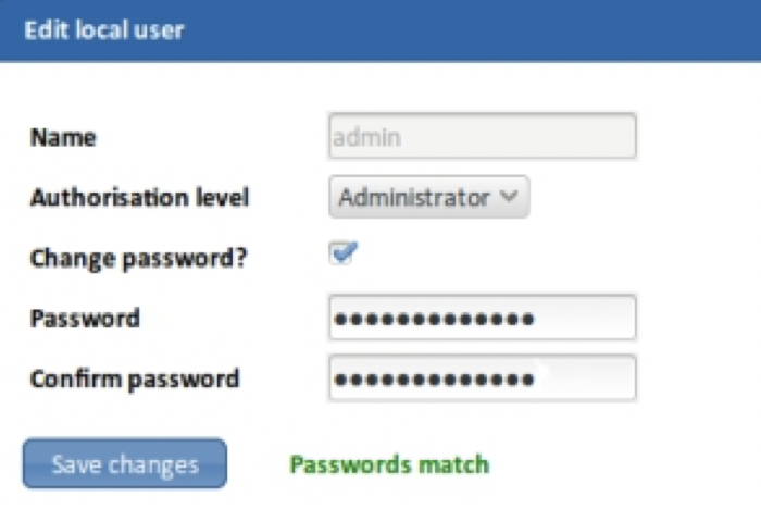
5. Select the Change password? checkbox.
6. Enter a new password for the Administrator account. Passwords must not contain spaces and can be up to 1-80 alphanumeric characters in length.
7. Click Save changes.
8. Reset the passwords for the Operator and Audit accounts using the same procedure.
9. Click Review/apply and review pending changes. To apply these changes to the system, click Apply changes or click ‘X‘ to cancel.
Equivalent CLI commands for changing management passwords are follows:
CONTROLLER>show users
user : security level 2
admin : security level 3
audit : security level 1
CONTROLLER>set user Admin password new-password
Changing password for user Admin
CONTROLLER>set user User password new-password
Changing password for user User
CONTROLLER>set user Audit password new-password
Changing password for user Audit
Managing the system time
Network time synchronization is critical because every aspect of managing, securing, planning, and debugging a network involves determining when events occur. Time also provides the only frame of reference between all devices on the network.
Without synchronized time, accurately correlating log files between these devices is difficult, even impossible.
A few of the specific reasons include, tracking security breaches and network usage. Problems affecting a large number of components can be nearly impossible to track if timestamps in logs are inaccurate. Time also reduces confusion in shared file systems, as it is important for the modification times to be consistent, regardless of the machine on which the file systems reside.
For
these reasons,
it is important that the time configured on the all devices on the network be accurate.
The KARINCA-1048-6C device supports Network Time Protocol (NTP) and when enabled, the device dynamically synchronizes the device time with the NTP server time. The device operates only as an NTP client, and cannot provide time services to other devices.
Adding an NTP server
KARINCA-1048-6C can be configured to synchronize with your network NTP server.
1. Click on the chassis and select the Security tab.
2. In the NTP server field, enter the IP address of the network NTP server.
3. Click Review/apply and review pending changes. To apply these changes to the system, click Apply changes or click ‘X‘ to cancel.
Saving the current configuration
Administrators can save the current configuration to permanent memory to create a backup of port settings, port maps, port maps, packet filters, and the SNMP configuration. User accounts and network settings are not saved, however.
1. Click on the chassis and select the Management tab.
2. Click Saved configurations. The Saved configurations dialog displays.
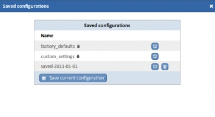
3. Click Save current configuration and enter a name for the configuration. Configuration names may contain up to 80 alphanumeric characters plus the underline character (’_’). Spaces are not permitted.
4. Click Save to save the configuration.
The equivalent CLI command for saving the current configuration is as follows:
CONTROLLER>create settings filename
Loading a configuration
You can load a configuration from permanent memory to restore ports, maps, filters and SNMP settings to a previous state. For example, you can restore the system to its factory default settings by loading the factory_defaults configuration. You must be an Administrator to restore a configuration.
1. Click on the chassis and select the Management tab.
2. Click Saved configurations. The Saved configurations dialog displays with a list of available configurations. Depending on your system installation, you may have several default configurations that have been pre-installed. For example, all system have a factory_defaults configuration that can be used to reset the system back to its factory configuration. Other default configurations may exist on your system.
3. Select the configuration to restore and click the load icon .
4. Click Load to load the configuration and overwrite the current configuration.
Using the CLI to restore a configuration
From the command line, you can restore a configuration from permanent memory using the create settings command and the name of the configuration.
For example, to restore the configuration named My_KARINCA-1048-6C _configuration, enter the following command:
CONTROLLER>restore My_KARINCA-1048-6C_configuration
applied settings OK
Downloading the system configuration
You can download the system configuration to a text file for backup or transfer to another KARINCA-1048-6C device. The configuration file is a complete backup of the system, and includes network interface settings and user accounts with passwords removed.
The backup must not be used without first editing the network settings and user accounts. Failure to do this may prevent access to the device for all users.
1. Click on the chassis and select the Management tab.
2. Click Download configuration. If necessary, accept the option to open a pop-up window in your browser.
3. Copy all of the configuration information to text file and save it. Do not use spaces or other special characters in the filename.
4. Close the pop-up window when you have finished.
Uploading a system configuration
You can upload a system configuration to restore the system. When you do this, all current configurations for ports, network and user accounts are overwritten by the new configuration.
To prevent becoming locked out of the system, only upload KARINCA-1048-6C configuration files that have the correct network setting and user account names and passwords in place. Use a text editor to edit the configuration file as necessary.
1. Click on the chassis and select the Management tab.
2. Click Upload configuration file, and click Continue. You will now be logged out of the system.
3. Enter the Administrator username and password, click Choose file and navigate to the file you want to load.
Upgrade system firmware
Angora Networks may occasionally release new versions of the system firmware to upgrade device functionality and enhance performance.
Firmware updates should be scheduled for maintenance periods. Upgrading the system software may cause fundamental changes to the device’s operation and affect links for several minutes.
To upgrade the system firmware
1. Click on the chassis and select the Management tab.
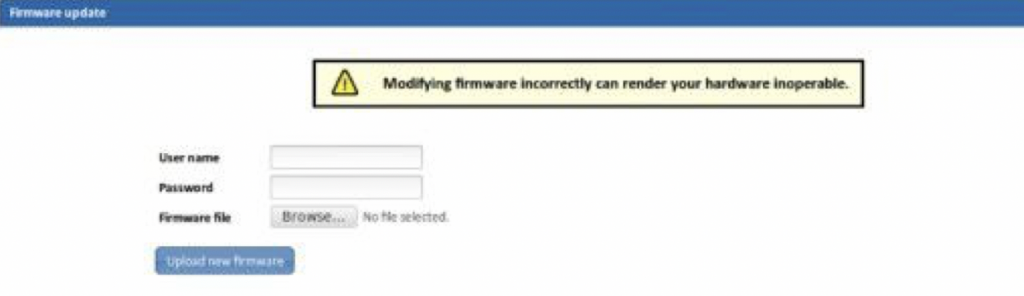
2. Click Update, and then click Continue.
You will be logged out and the Firmware update window will be displayed
3. Enter the Administrator username and password, and browse to the firmware file.
Applying incompatible firmware may render the device inoperable. Before applying a firmware update always check the file is compatible with your device. Contact Angora Networks Support for advice if you are unsure.
4. Click Upload new firmware.
The firmware upgrade takes a few minutes to complete, during which time you must not power off the device.
Installing a Feature Pack
Administrators can install Feature Packs to add additional port capabilities to the system, including filtering and load balancing. Each Feature Pack adds the advertised capabilities to up to 54 floating ports.
1. Click on the chassis and select the Management tab.
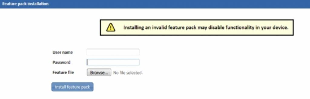
2. Click Install features, and then click Continue.
You will be logged out and the Install Features window will be displayed (see figure below).
3. Enter the Administrator username and password, and browse to the feature pack file supplied by Angora Networks.
Installing an invalid feature pack may disable functionality in your device. Contact Angora Networks Support for advice if you are unsure.
4. Click Install feature pack.
Configuring system security
This section describes various aspects of security and access control. The system handles various types of security including, user access control, user authentication, and transaction accounting.
Managing public host keys
KARINCA-1048-6C includes a default RSA public host key to verify that the host key presented during an SSH connection is in fact KARINCA-1048-6C ’s.
The first time you connect to KARINCA-1048-6C with an SSH client, the client will warn you that the host keys are not in your local cache and show you the actual host key presented by KARINCA-1048-6C . Your client will most likely give you the option of trusting the key, adding it to your local cache (see the following example output).
The authenticity of host '192.168.254.100' can't be established.
RSA key fingerprint is 9a:30:7b:95:ec:b4:fe:53:e1:a4:42:69:4f:15:5c:1a.
Are you sure you want to continue connecting (yes/no)? yes
Warning: Permanently added '192.168.254.100' (RSA) to the list of known hosts.
Once you’ve trusted the key, your client will alert you during connection if a different key is presented. You may also upload your own public key certificates to replace the default public-key.
Changing public host keys
You can use the Upload SSL certificate option in the web UI to change the default public host keys provided with KARINCA-1048-6C . Note, there is no facility for changing public hosts keys from the CLI.
1. Click on the chassis and select the Management tab.
2. Click Upload SSL certificate, and then click Continue. The Upload SSL certificate page displays.
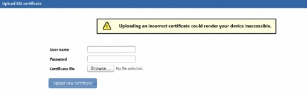
3. Enter the Administrator username and password, and browse to the certificate file.
The certificate file must be in a .tar.bz2 file format, and must contain the following two files only:
- Angora Networks.crt—X.509 certificate file (PEM-encoded; maximum 8192 bits)
- server.key—private key file (PEM-encoded; maximum 8192-bit)
Uploading an incorrect certificate could render the device inaccessible to network connections. If this happens, you should connect via the serial Console port and perform a factory reset with instructions from Angora Networks Support.
4. Click Upload new certificate and wait for the certificate file to be uploaded and verified. All new connections will be verified using the new public-keys.
Configuring management access
You can assign authentication methods to management access methods, such as SSH, console, and HTTPS. This authentication can be performed locally or on an external server, such as a TACACS+ or a RADIUS server.
User authentication occurs using the authentication methods that are selected, in no particular order. If the first authentication method is not available, the next selected method is used. For example, if the selected authentication methods are RADIUS and Local, and all configured RADIUS servers are queried in priority order and do not reply, the user is authenticated locally. If an authentication method fails or the user has insufficient privilege level, the user is denied access to the device. In other words, if authentication fails at an authentication method, the device stops; it does not continue and does not attempt to use the next authentication method.
Defining authentication methods for access
1. Click on the chassis and select the Security tab.
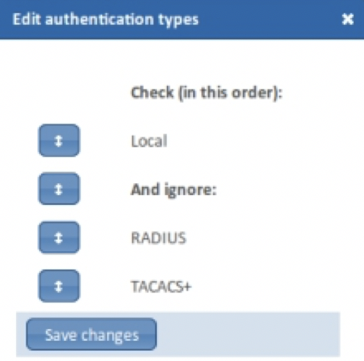
2. Click on the icon next to Authenticate users. The Edit authentication types dialog displays
3. Drag authentication methods into the desired order. Any authentication methods that are not required should be placed below And ignore:, which can also be dragged into position. The following authentication methods are available:
- Local—Username and password is checked against the data stored on the local device. These username and password pairs are defined in the Local Users dialog.
- RADIUS—User is authenticated on a RADIUS server. You must have configured one or more RADIUS servers.
- TACACS+—User authenticated on the TACACS+ server. You must have configured one or more TACACS+authentication servers.
4. Click Review/apply and review pending changes. To apply these changes to the system, click Apply changes or click ‘X‘ to cancel.
Configuring TACACS+ authentication servers
The KARINCA-1048-6C device can be configured as a Terminal Access Controller Access Control System (TACACS+) client that relies on a TACACS+ server to provide centralized security, authorizing and authenticating users attempting to access and administer the unit.
TACACS+ provides the following services:
- Authentication—Provides authentication of administrators logging onto the unit by using usernames and user-defined passwords.
- Authorization—Performed at login. After the authentication session is completed, an authorization session starts using the authenticated username. The TACACS+ server then checks user privileges.
- Accounting—Enable accounting of login sessions using the TACACS+ server. This enables a system administrator to generate accounting reports from the TACACS+ server.
After the authentication session is completed, an authorization session starts using the authenticated username. The TACACS+ server then checks user privileges. The TACACS+ protocol ensures network integrity, through encrypted protocol exchanges between the device and the TACACS+ server.
TACACS+ is supported only with IPv4.
TACACS+ servers cannot be used as 802.1X authentication servers to verify credentials of network users trying to join the networks through the unit.
Some TACACS+ servers support a single connection that enables the device to receive all information in a single connection. If the TACACS+ server does not support this, the device reverts back to multiple connections.
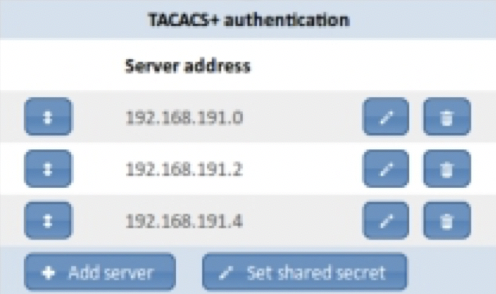
TACACS+ authentication servers can be configured using the TACACS+ authentication dialog, shown below.
TACACS+ workflow
This device uses CHAP (Challenge-Handshake Authentication Protocol) when authenticating users with the TACACS+ server. To use a TACACS+ server, do the following:
1. Open an account for a user on the TACACS+ server.
2. On that server, configure the user or group privileges to 1 for an Audit user, 2 for an Operator, or 3 for an Administrator. For example, privilege level 2 is given to a user or group of users on the TACACS+ server by the following string in the user or group definition:
service = exec { priv-lvl = 2 }
3. Specify TACACS+ as the authentication method, so that when a user logs onto the device, authentication is performed on the TACACS+ server instead of locally.
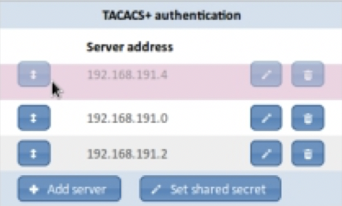
If more than one TACACS+ server has been configured, the device uses the configured priorities of the available TACACS+ servers to select the TACACS+ server to be used by the device. As shown in the following figure, server priority can be changed by dragging the servers into the required order. Servers at the top of the list have the highest priority.
Configure TACACS+ authentication servers
1. Click on the chassis and select the Security tab.
Existing TACACS+ authentication servers
are shown in the TACACS+ authentication dialog.
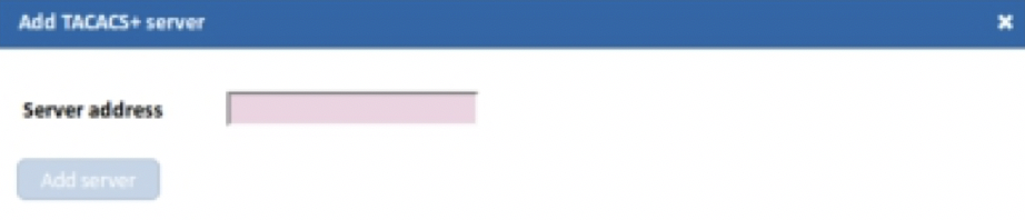
2. To add a new TACACS+ community, click Add server, or, to edit an existing community, click the icon for that server. The Add TACACS+ server dialog displays, shown below.
3. Enter the IPv4 address of the TACACS+ authentication server and click Add/Save. The server is added to the list of TACACS+ authentication servers.
4. If several servers have been configured and you wish to prioritize the order in which they are contacted, use the Arrange icon to drag servers into position. Servers at the top of the list have highest priority and are contacted first.
5. Click Set shared secret and enter the shared secret for your TACACS+ authentication server(s).
6. Click Review/apply and review pending changes. To apply these changes to the system, click Apply changes or click ‘X‘ to cancel.
Configuring RADIUS authentication servers
Remote Authorization Dial-In User Service (RADIUS) servers provide a centralized 802.1X or MAC-based network access control. The device is a RADIUS client that can use a RADIUS server to provide centralized security.
An organization can establish a Remote Authorization Dial-In User Service (RADIUS) server to provide centralized 802.1X or MAC-based network access control for all of its devices. In this way, authentication and authorization can be handled on a single server for all devices in the organization.
The device can act as a RADIUS client that uses the RADIUS server for the following services:
- Authentication—Provides authentication of regular and 802.1X users logging onto the device by using usernames and user-defined passwords.
- Authorization—Performed at login. After the authentication session is completed, an authorization session starts using the authenticated username. The RADIUS server then checks user privileges.
- Accounting—Enable accounting of login sessions using the RADIUS server. This enables a system administrator to generate accounting reports from the RADIUS server.
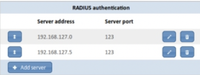
RADIUS authentication servers can be configured using the RADIUS authentication dialog, shown below.
RADIUS workflow
This device uses PAP (Password Authentication Protocol) when authenticating users with the RADIUS server. To use a RADIUS server, do the following:
1. Open an account for the device on the RADIUS server.
2. In that server’s radiusd.conf configuration file, add users and configure the Reply-Message attribute so that it contains “audit”, “user”, or “admin” for the respective Audit, Operator, and Administrator account. For example:
user1 Cleartext-Password := “User1Password
Reply-Message = "audit"
user2 Cleartext-Password := “User2Password
Reply-Message = "user"
user3 Cleartext-Password := “User3Password
Reply-Message = "admin"
3. Specify RADIUS as the authentication method, so that when a user logs onto the device, authentication is performed on the RADIUS server instead of locally.
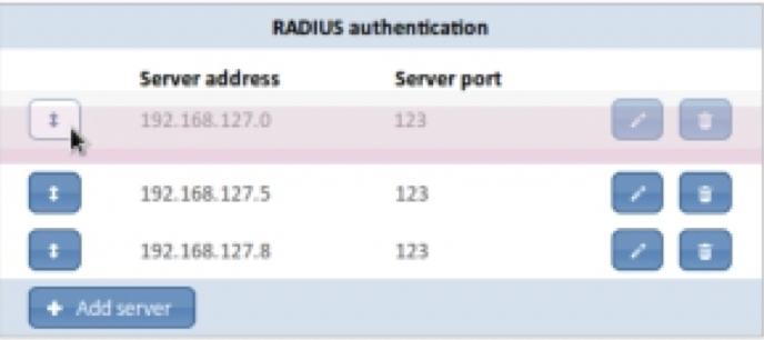
If more than one RADIUS server has been configured, the device uses the configured priorities of the available RADIUS servers to select the RADIUS server to be used by the device. As shown in the following figure, server priority can be changed by dragging the servers into the required order. Servers at the top of the list have the highest priority.
Configure RADIUS authentication servers
1. Click on the chassis and select the Security tab.
Existing RADIUS authentication servers are displayed in the RADIUS authentication server dialog.
2. Click Add server.
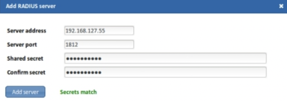
3. In the Add RADIUS server dialog (shown below), enter the parameters:
- Server address—Enter the server’s IPv4 address.
- Server port—Enter the UDP port number, usually port 1812 for RADUS authentication servers.
- Shared secret—Enter the RADIUS server’s shared secret.
- Confirm secret—Enter the shared secret again to confirm it.
4. Click Add server. The server is added to the list of RADIUS accounting servers.
5. If desired, arrange server priority by dragging with the Arrange control. Servers at the top of the list are contacted first.
6. Click Review/apply and review pending changes. To apply these changes to the system, click Apply changes or click ‘X‘ to cancel.
Managing transaction logging
Accounting gives the ability to track usage, such as user access, the ability to log the data gathered to a database, and the ability to produce reports on the data gathered.
Although the KARINCA-1048-6C does not locally support accounting, you can enable an AAA accounting server running RADIUS or TACACS+ and have accounting information logged by the AAA server.
Add TACACS+ accounting servers
1. Click on the chassis and select the Security tab.
Any existing TACACS+ accounting servers are shown in the TACACS+ accounting dialog, shown below.
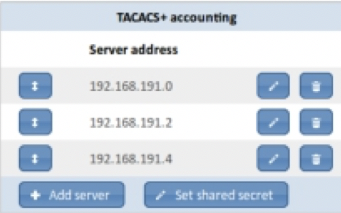
2. Click Add server and enter the IPv4 address of the TACACS+ accounting server. The server is added to the list of TACACS+ accounting servers.
If you have multiple servers set up, you can organize server priority with the Arrange by dragging theservers into the required order. Servers higher up the list have higher priority than those further down and will be contacted first.
3. If you have not done so already, click Set shared secret and enter the global shared secret for the TACACS+ accounting servers.
4. Click Review/apply and review pending changes. To apply these changes to the system, click Apply changes or click ‘X‘ to cancel.
Add RADIUS accounting servers
1. Click on the chassis and select the Security tab.
Any RADIUS accounting servers already been set up will be shown in the RADIUS accounting server list, shown below.
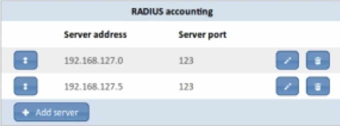
2. Click Add server and enter the RADIUS accounting server’s parameters in the Add RADIUS server (shown below):
- Server address—Enter the RADIUS server’s IPv4 address.
- Server port—Enter the UDP port number, usually port 1813 for RADUS accounting servers.
- Shared secret—Enter the RADIUS accounting server’s shared secret.
- Confirm secret—Enter the shared secret again to confirm it.
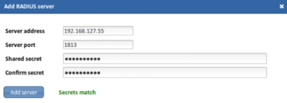
3. Click Add server. The server is added to the list of RADIUS accounting servers.
If you have multiple servers set up, you can organize server priority with the Arrange control by dragging the servers into the required order. Servers higher up the list have higher priority than those further down and will be contacted first.
4. Click Review/apply and review pending changes. To apply these changes to the system, click Apply changes or click ‘X‘ to cancel.
Rebooting the system
You can reboot the device to reset all components of the system to the last saved/applied configuration. Any pending updates will be lost unless applied prior to rebooting.
A reboot takes around 2–3 minutes. During this time you will be unable to login to the system and all network traffic on the live ports will be stopped, including copper ports with TAP mode/failsafe enabled.
Reboot the system
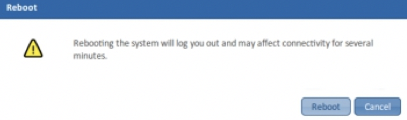
1. Click on the chassis and select the Management tab.
2. From the management options, click Reboot. The Reboot dialog displays (see figure below).
3. Click Reboot. The device will now reboot. All traffic entering/leaving the device will be stopped for 2–3 minutes while the device reboots.
Leave A Comment?