Using filters
You use filters by first defining them and then applying them to a map. Filters can be combined or used in parallel to create filtering rules that are able to match only those packets of interest from the entire data stream.
To use a filter, first define it by giving it a name and choosing the headers you want to filter for. After defining the filter, add it to a map as either a require or an exclude filter:
- A require filter passes packets matching the filtering criteria and rejects packets which do not
- An exclude passes packets which do not match the filtering criteria and rejects packets which do
When a filter has been applied its label appears beside the map, along with the word NOT if the filter is an exclude filter. More complex filtering rules can be created by:
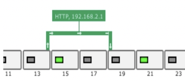
Applying multiple filters to a single map, as shown in the following figure. This combination only passes packets when all require filters and no exclude filters match (a logical AND).
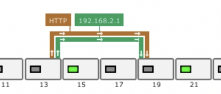
Applying multiple filters to several maps in parallel, as shown in the following figure. This combination passes packets matching all required filters and no exclude filters for any one of the parallel maps even if that packet would not pass some of the filters on the other maps that are created in parallel between the same ports (a logical OR).
Defining filters
Use the Add/Edit filter dialog to define filters.
1. Click on the chassis and select the Filters tab.
2. Click Add new filter, or click to edit an existing filter.
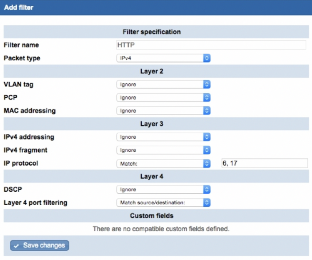
3. Enter a unique name for the filter. The name will be used to label maps where the filter is applied.
4. From Packet type, select the packet type to filter on. The packet type corresponds approximately to the EtherType in the packet header, and determines which additional layer 2, 3 and 4 filter fields are available.
5. If required, refine the filter by specifying layer 2, 3 and 4 filtering criteria.
6. If required, further refine the filter by adding a custom field. Only custom filters which match the packet type are shown. Specify the values to match in the custom field.
A custom field is “in use” if at least one filter that is required or excluded by at least one map specifies a value to match for that field.
7. Click Add filter to finish defining the filter.
8. Click Review/apply and review pending changes. To apply these changes to the system, click Apply changes or click ‘X‘ to cancel.
Packet header filtering criteria
List of Layer 2, 3 and 4 headers available for packet filters. The system will prevent you from selecting headers which are incompatible with the specified packet type. For instance, you cannot choose IPv6 packets and IPv4 fragments, or MPLS and VLAN tags.
Table 1: Layer 2 headers
| Header type | Filtering options |
| VLAN tag | Filters by VLAN number. The following caveats should be noted when filtering by VLAN: When a filter is set to permit VID 1, untagged packets will still be forwarded. Tagged packets with a VID of 1 will be forwarded untagged. Tagged packets with a VID of 0 will be dropped. You may use the following formats when specifying tags: 100: A single tag 100-110: An inclusive range 0/1: A value/mask pair (here: all even tags) 100, 150: Multiple tags may each use a range or mask. |
| PCP | Filters by Priority Code Point (user priority) from a VLAN header. You may use the following formats when specifying levels: 2: A single level 2-4: An inclusive range 0/1: A value/mask pair (here all even) 0,2: Multiple levels |
| MAC addressing | Filters by MAC address. You may give either a single specification to find packets where either the source or the destination address matches, or separate specifications for source and/or destination address. You may use the following formats when specifying MAC addressing: 01:23:45:67:89:ab: A single address 01:23:45:67:89:ab, 01:23:45:67:89:ac: Multiple addresses For ARP packets use source for the sender address and destination for the target address. |
| MPLS top of stack label | Filters by MPLS label. Where the MPLS header for a packet contains multiple labels, this will test the top label in the stack. You may use the following formats when specifying labels: 100: A single label 100-110: An inclusive range 0/1: A value/mask pair (here: all even labels) 100, 150: Multiple labels. Multiple labels may each use a range or mask. |
Table 2: Layer 3 headers
| Header type | Filtering options |
| IPv4 addressing | Filters by IPv4 address. You may give either a single specification, to find packets where either the source or the destination address matches, or separate specifications for source and/or destination address. The following formats can be used to filter on a single IPv4 address, a range of addresses, or multiple addresses: 192.168.0.1: A single address 192.168.0.4-10: An inclusive range 192.168.0.*: Wildcard (192.168.0.0-255) 10.10.0.0/255.255.255.252: Mask (10.10.0.0-3) 10.10.0.3, 10.10.0.5:Multiple addresses Ranges and wildcards may be used in any segment(s). Multiple addresses may each use either ranges and wildcards or a mask. For ARP packets, use source for the sender address and destination for the target address. |
| IPv4 fragment | Filters by IPv4 fragments. Enter 0 not a fragment, or 1 is a fragment. |
| IP protocol | Filters by IP protocol number. Some commonly used IP protocols numbers are: 1: ICMP 6: TCP 17: UDP 132: SCTP The following formats can be used to specify a single protocol, a range of protocols, or multiple protocols: 1:A single protocol 1-2: An inclusive range 0/1: A value/mask pair (here: all even protocols) 6, 17: Multiple protocols. Multiple protocols may each use a range or mask. |
| IPv6 addressing | Filters by IPv6 address. You may give either a single specification to find packets where either the source or the destination address matches, or separate specifications for source and/or destination address. The following formats can be used to filter on a single IPv6 address, a range of addresses, or multiple addresses: 2000:abcd:0:0:0:0:77:88 : A single address 2000:abcd::77:88 : A single address (eliding a single run of zero segments) 2000:abcd::77:88-99: A range address (inclusive) 2000::* : A wildcard (here: 2000::0-ffff ) ::ffff:0:0/96: Prefix (any address starting 0:0:0:0:0:ffff ) 2000::1, 2000::3: Multiple addresses may each use either ranges and wildcards or prefix notation. Ranges and wildcards may be used in any segment(s). |
Table 3: Layer 4 headers
| Header type | Filtering options |
| DSCP | Filters DSCP number. Separate multiple DSCP numbers with commas. The following formats are recognized: 10: a single code point 10–14: An inclusive range 0/1: a value/mask pair 10, 12, 14: multiple code points. Multiple code points may each use a range or mask. |
| Layer 4 port filtering | Filters by TCP/UDP port number when protocol number 6 (TCP) or 17 (UDP) is specified in Layer 3. You may enter either a single specification to find packets where either the source or the destination port matches, or separate specifications for source and/or destination port. Common TCP ports include: 80, 8080: HTTP 443: HTTPS 25: SMTP 20-21: FTP 989, 990: FTPS 22: SSH 23: Telnet |
| FIN, SYN, RST, PSH, ACK, URG, ECE, CWR | Filters on the specified flag. For each flag the following values may be set: 0: Flag not set 1: Flag set |
| ICMPtype | Filter by ICMP type when filtering by ICMP packet (protocol number 1). The following formats are recognised: 10: A single type 10–14: An inclusive range 0/1: A value/mask pair (here: all even types) 10,12,14: Multiple types (use commas to separate values, no spaces). Types may each use a range or mask. |
| ICMPcode | Filter by ICMP code when filtering by ICMP packet (protocol number 1). The following formats are recognised: 10: A single code 10–14: An inclusive range 0/1: A value/mask pair (here: all even codes) 10,12,14: Multiple codes (use commas to separate values, no spaces). Codes may each use a range or mask. |
Defining custom fields
You can use custom fields to filter on user-defined bytes (UDBs) in a packet header. The positioning of the custom field within the packet is done by specifying an anchor and an offset value. The custom field itself can be up to 32 bits long.
Custom fields are applied by defining a filter of the same packet type, and specifying the custom field and UDBs that you want to apply to the filter.
The following limitations apply for custom fields:
- No more than two underlying user-defined bytes anchored on start-of-packet can be used at once.
- No more than three underlying user-defined bytes can be used in conjunction with other filtering on IPv6 headers for traffic from the same ingress port.
- No more than six underlying user-defined bytes can be used in total at any given time.
Here, “used” refers to custom fields that can actually affect passing traffic. Other custom fields may still be defined, and filters may be defined using them, but these don’t count toward the totals as long as the filters aren’t applied to any maps.
1. Click on the chassis and select the Custom fields tab.
2. Click Add new custom field, or click to edit an existing custom field.
3. Enter a unique name for the custom field. This name will be available in the Custom fields section in the filter definition screen if the packet type you choose when defining the filter is compatible with the scope of any custom fields you’ve defined.
4. Enter details for the custom field:
- Scope—Select what types of filters may use the custom field, either all, all IP, IPv4, IPv6, ARP, or MPLS filters.
- Anchor—Select the starting position of the custom field in the packet, either at the start of the packet, at the start of the layer 3 header, at the start of the layer 4 header, or at the start of the IPv6 extension header.
- Offset—Enter an offset position relative to the anchor position for the start of the field. You may enter offset values of 0–1007 bits.
- Length—Enter a length for the field. The field length can be 1–32 bits. The offset plus the length of the field must not exceed 1008 bits.
5. Click Add custom field to finish defining the custom field.
6. Click Review/apply and review pending changes. To apply these changes to the system, click Apply changes or click ‘X‘ to cancel.
Applying filtering
To apply filtering, click on a map, select the relevant filter(s) from the list of defined filters, and choose either Ignore (let all packets pass), Require (let only matching packets pass), or Exclude (let only non-matching packets pass).
1. If you haven’t done so already, set up the port mappings and define your filters.
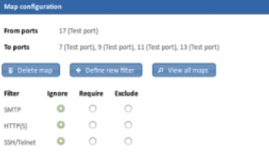
2. Click on a map. A list of defined filters is shown, as shown in the figure below.
3. For each filter in the list, choose how you want filtering to be applied to the map:
- Ignore—(Default setting) Ignore this filter; let all packets pass.
- Require—Pass all matching packets and drop all non-matching packets.
- Exclude—Drop all matching packets and pass all non-matching packets.
4. Click Review/apply and review pending changes. To apply these changes to the system, click Apply changes or click ‘X‘ to cancel.
Leave A Comment?