Angora edge switches can be stacked to allow 8 switches of different models to be managed as a single switch. This way, it provides support for up to 400 available ports.
Stacking Features
Stacking Topologies
There are two switches that has special tasks within the stack. Master and backup switches take over the entire management. Other switches remain in slave status.
The network administrator can remotely manage the entire stack with a single IP address, regardless of the stack topology.
The stack topology can be a ring or chain. In ring topologies, each switch is connected to two switches. In chain topologies, two switches in the stack are connected to one switch. The figure below shows the connection architecture of the two topologies.
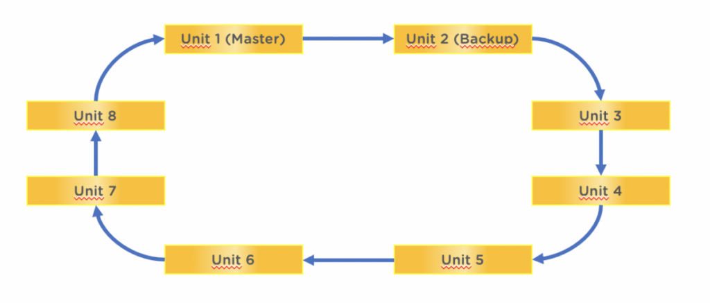
Ring Topology
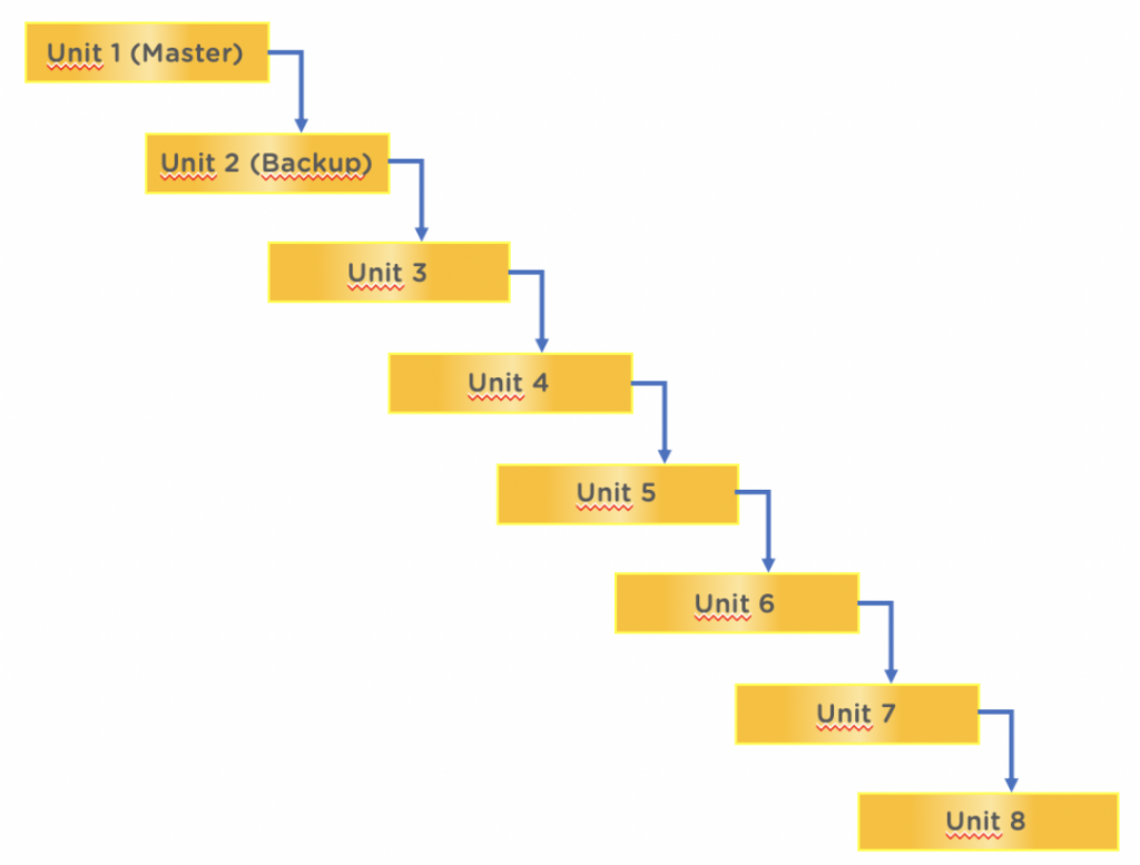
Chain Topology
While booting a stack group, the master switch selection and topology discovery algorithms starts, to control the entire stack. After the master switch is selected, the slave switches only transmit the key information to which they are connected and start waiting. The master switch builds the stack tree with all topological information. Depending on the structure of the topology formed, the traffic is carried between the devices in a balanced way. Multicast traffic in particular, passes through both links in the stack, and provides more effective use of the links.
Stack Management
The stack is managed by the master switch. All stack information is collected in the master switch, processed and copied to the backup switch.
The software management of the switches in the stack can be done by the master switch. It is possible to update the software of the devices in the stack with the ‘copy’ command from command line.
Software Synchronization
Different software versions are not supported in the stack. All switches must use the same software as a member of the stack. When a new device is added to the stack, this device checks for compatibility. This control confirms the ability of the master switch to change the new device version. If the verification is successful, the new device is brought to its own software version by the master switch. If verification fails, new device ports are closed.
The compatibility check consists both software and hardware. For compatibility status, please contact Angora Networks authorized technical partner.
If the master device synchronizes the software of the slave devices, a syslog message is sent. The sent message contains the following parameters:
- Slave switch number
- Slave switch current software version
- Master switch software version (sent to slave)
- If there was a problem with the version update; cause of error
Console access
On stacked switches, only the console port on the master device can be actively used. Events on all other devices can be seen on the command line connected via the master switch console. It is not possible to send commands or view events from console interfaces of other devices.
Member device numbers
Each device capable of stacking has a unique member number (Unit ID). This number is automatically selected when the stack is first created and then be changed from the master device.
This number is used by the ‘Stacking Algorithm’ that works on all stack members to name the device in the stack. This algorithm checks the status of stack members and the data flow between the stack elements.
If two devices are given the same member number when defining stack numbers, only one of these devices can become a member of the stack. When choosing a member, first criteria is how long the device has been working, the age of the device (uptime) are taken into consideration. If the ages of the devices are the same, the device that will have the least impact on the stack is disabled.
Devices that are in the same 10-minute slot are considered the same age.
Standalone or Stack
Each device can work as standalone or as part of a stack. The decision on which the device will operate, is determined during device boot. To change the working state, you need to restart the device. When the device is first purchased, it will be set to operate in standalone mode.
Operating states of the devices in stack
Inside a stack, devices can operate under ‘Master’, ‘Backup’ and ‘Slave’ states.
The master device is responsible for all switch software management. It is also responsible for the configuration of other switches as the main administrator of the “Distributed Switching Application”. This application manages the low-level drivers of other switches, ensuring the switching process runs smoothly. All protocols operate in master device’s management. The identification number of the master device is either 1 or 2.
The backup device works like a slave in normal operation. In addition, it constantly checks the existence and operation of the master device. If there is a problem with the master device, the backup device takes over all the roles of the master device (switchover). This task change takes a maximum of 30 seconds.
Determining device operating states
If a value between 3 (three) and 8 (eight) is entered as the Unit ID in a device configuration, that device will work as a slave. If the ID number is 1 or 2, this device can be either a master or a backup. No identification number has been entered on the devices purchased. Thus, it is not included in the stack selection process at startup and switch works as standalone.
Administrators can change the ID number when the device is turning on or after the configuration loaded.
If the master device becomes unusable for some reason and the backup device is available, the switchover process starts and the backup device becomes the master device.
In the operating state, the ‘operator’ command enables master transition.
If the devices in the stack are disconnected or become inoperative (electrical issues, software problems, etc.), the device becomes unusable and all ports are closed.
Master device selection
Two devices with ID numbers 1 and 2 can be selected as primary and backup in the stack. The master device selection algorithm operates between two devices that may be essential and operate as follows:
When a potential master device is added to the stack (or when the master and backup devices are turned on at the same time), the two devices share information with each other on how long they have been running. If the difference between these times is less than 10 minutes, the device with the smallest identification number becomes the primary device. If the difference is more than 10 minutes, the device that has been open for a longer time will act as the main device.
The master device centrally manages the entire stack. The ports on the slave devices seem to be on the main device, so that administrators can manage the entire stack as if they are managing a single device.
If the master or backup device is removed from the stack and one of the slave devices is desired to be assigned to these tasks, the slave device identification number must be reconfigured and the device must be restarted.
If desired, the backup device can be converted from the command line to the master device, despite the selection algorithm decision.
In case master device fails
The master and backup device wait ready for possible problems with the ‘cold backup’ approach. In case of a problem, the backup device takes full management and resumes normal operation without creating an interruption.
In the cold backup approach, the configuration is exactly synchronized between the two devices. Dynamically created tables such as STP tables, learned MAC addresses, multicast tables, LACP tables are not synchronized. When the backup device is activated, the protocols are restarted and the calculations are made again and the tables are re-created. No package is sent to this device until the backup device is activated. With the exception of this instant action, no packet loss occurs.
The synchronization applies to both the running configuration and the boot configuration. Synchronization occurs as soon as the configuration changes.
When a device enters the stack as a backup, the master device immediately sends the current configuration to this new backup device and completes the synchronization.
When a device from a different stack enters a new stack and begins to act as a backup, it will take the configuration of the new stack and forget the old stack configuration.
Stack Cabling
Cables used for stack operation are standard Multi-Mode fiber cables. Stack connections are made through the devices’ 10Gbit SFP + ports. All standard cable and fiber interfaces are used. There is no need for any special accessories.
Interruptions in stack topology
Failure of a device in the stack, adding a device to the running stack, or connectivity issues cause changes in the topology and is managed by the master device. Such situations may cause the topology to transform from ring topology to chain topology. In some cases, it may even result in the stack being split into two independent parts.
In all these cases, the master device detects the topology change and ensures the normal operation of the stack. Turns off the ports of inaccessible devices but keeps all configuration related to these ports.
In some cases, slave switches become unable to access any master or backup devices.Since there are no tables for switching, switching would not take place. In this case, administrator intervention is required.
If the backup device is removed from the stack, it retains the last configuration it received. If this device connects to another stack and becomes the master or backup device, it uses the configuration of the new stack.
Adding a new device and reconnecting the cable
In the normal operation of the stack, when a new device is added (or a problem on cables is fixed), the topology change is triggered. As the stack continues to operate normally, the new device or connection is configured.
The recommended procedure for adding new devices to the stack is as follows:
- The device mounted in its physical location and the cables required for the stack are connected (the connection to the rest of the stack is not made yet) and without power.
- When it is time to set an identity, an identity is defined.
- After this point, stack connection is made with the new device.
Configuring new device
The master device maintains a stack port table. This table is large enough to hold all the connections possible in a stack. Stack ports are defined by users. This configuration is kept by the master device, based on the device IDs. This table is updated as the device is added or removed from the stack. All changes in the stack are recorded in the event logs. Records are synchronized as soon as created between the master and backup devices.
Leave A Comment?